


We want to keep you in the loop! Our website is currently undergoing some exciting enhancements to provide you with an even better online experience.
A wireless power transfer system is a device which uses electromagnetic induction to provide electrical power without physical contact. They can be used for various applications, such as supplying power to moving or rotating devices, or devices sealed inside enclosed spaces. Because the primary and secondary sides do not touch, the power transmission efficiency and leakage flux vary depending on their positions relative to each other. Therefore, it is important at the design stage to understand how properties change according to their placement.
In order to use the wireless power transfer system efficiently, a precise and detailed analysis is required. The main objective of work is a magnetic analysis of a wireless power transfer system with cores (Fig. 1).
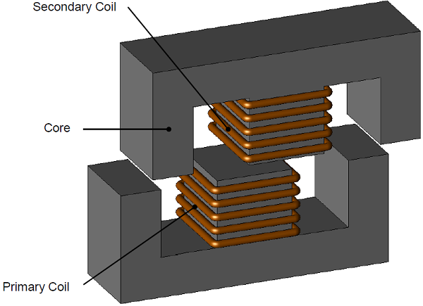
Fig.1 Geometry of a wireless power transfer system with cores
When evaluating the properties of a transformer whose primary and secondary sides are separated by a gap, it is helpful to use magnetic field analysis based on the finite element method (FEM), which allows precise modeling of the geometry of the parts and their relative positions, and make it possible to visualize the leakage in the magnetic flux that is generated in the primary side and transmitted to the secondary side. Magnetic frequency analysis is used for magnetic induction calculations in the system at source frequency 10 kHz.
Magnetic flux distributions are shown with vertical and horizontal displacement of secondary in Fig. 2 and Fig. 3. The leakage flux increases with displacement, which attenuate performance of the system.
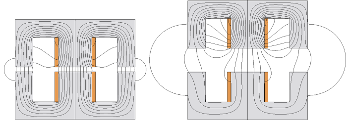
Fig.2: Magnetic flux distribution with and without vertical displacement
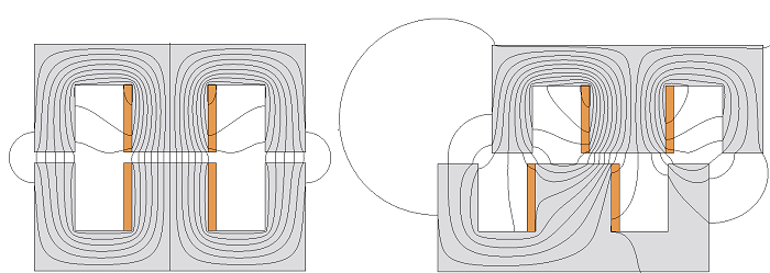
Fig.3: Magnetic flux distribution with and without horizontal displacement
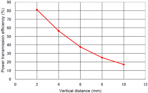
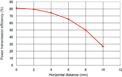
The efficiencies versus displacements are shown in Fig. 4 and Fig. 5., which decrease with higher displacement. Ferrite cores have been used for cores because of high source frequency and lower core losses.
 |
 |
|
|
Fig.4 Power transmission efficiency versus vertical distance |
Fig.5 Power transmission efficiency versus horizontal distance |
Magnetic flux densities are low in Ferrite cores (Fig. 6).
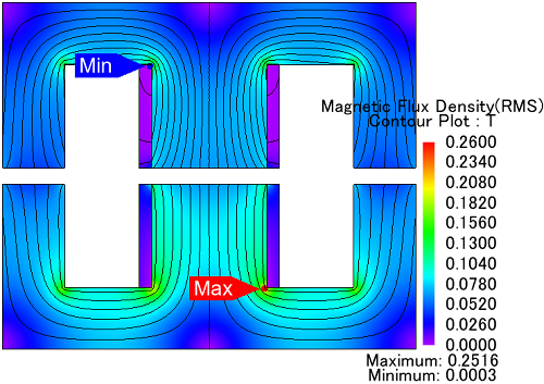
Fig. 6 Magnetic flux density distribution in Ferrite cores