


Electromagnetic forming using JMAG
and the CSE of Abaqus
1. Overview
Electromagnetic forming (EMF) is a type of high velocity, cold forming process for electrically conductive metals, most commonly copper and aluminium. The workpiece is reshaped by high intensity pulsed magnetic fields that induce a current in the workpiece and a corresponding repulsive magnetic field, rapidly repelling portions of the workpiece. The workpiece can be reshaped without any contact from a tool, although in some instances the piece may be pressed against a die or a former. In this paper, we present how to simulate and compute such an EMF using FEM software. JMAG is used to get the pulsed magnetic field, induced currents and the repulsive force; then Abaqus is used to get the deformation due to the force under the repulsive force constrain. We will also check the simulated resulting values of the force compare to actual measurements for a sample test model.
2. Coupling strategies
By combining the solvers of JMAG and Abaqus, the following two-way coupled analysis is possible:
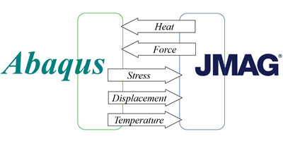
An analysis run by Abaqus uses results (force) from JMAG. Also, an analysis run by JMAG uses results from Abaqus (displacement). This coupled analysis supports “DYNAMIC” of Abaqus and its explicit solver.
3. Reference paper and experimental results
The experiment conducted by Takatsu et al. [N. Takatsu, M. Kato, K. Sato, T. Tobe, High-speed forming of metal sheets by electromagnetic force, Jpn. Soc. Mech. Eng. Int. J. 31 (1) (1988) 142.] was the free-bulging of a thin annealed Aluminum 1050 sheet. The below figure is the schematic of the axisymmetric experimental set-up. A conductive plate is placed on top of a five-turn pancake coil. The separation distance between the plate and the coil is approximatively 0.16 cm.

4. Electromagnetic force calculation
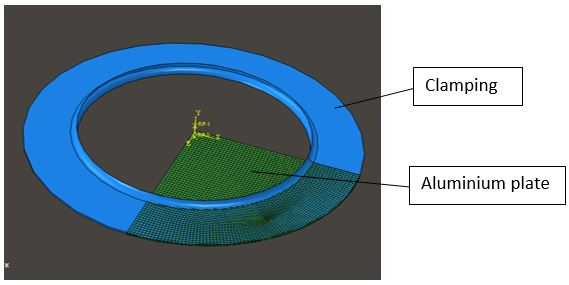
A quarter 3D electromagnetic model is down under JMAG:
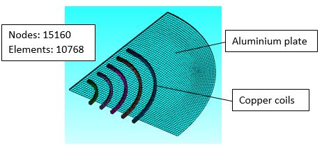
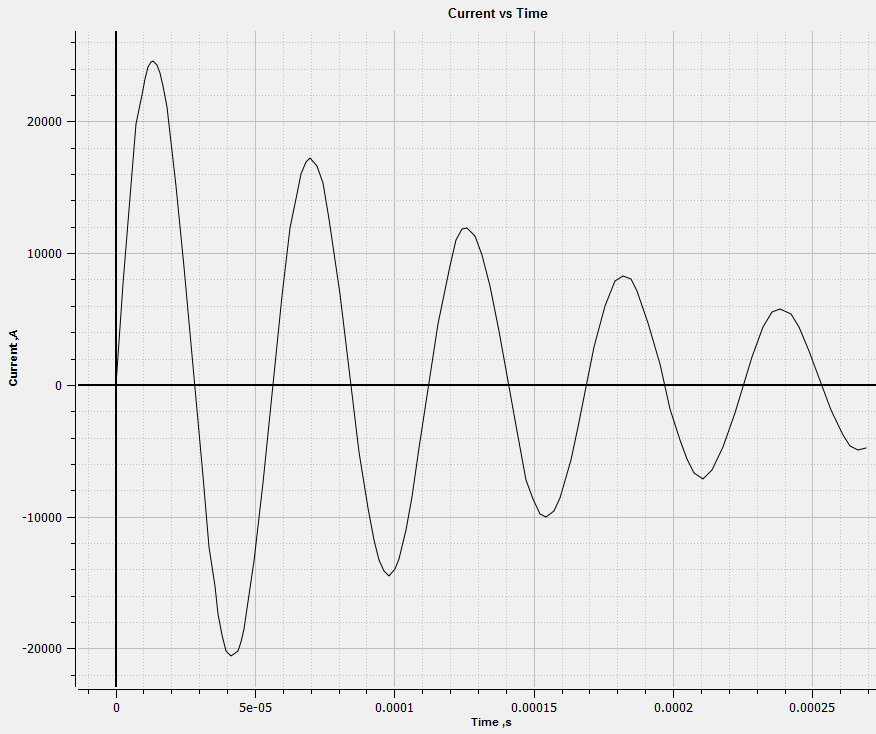
Materials are defined using standard properties. Conditions and electric circuit will be set up as describe in the reference paper. The campling parts are not needed in the magnetic calculation. The current impulse is the following one:
5. Deformation calculation
The 3D structural model is down in Abaqus:
Materials are defined using standard properties. The coil parts are not needed in the structural calculation.
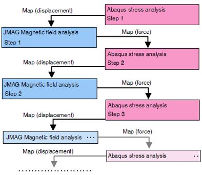
6. Coupling calculation
In JMAG, the scheduler is used to run a 2 way calculation. The Lorentz force is mapped from the JMAG results onto the Abaqus model. And the displacement is mapped from Abaqus onto the JMAG model. The mapping is down the common part from the both JMAG and Abaqus model: the aluminium plate.
7. Resulting date
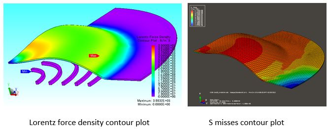
The below pictures shows the main results from the both simulations:
The total force magnetic force could also be compare:
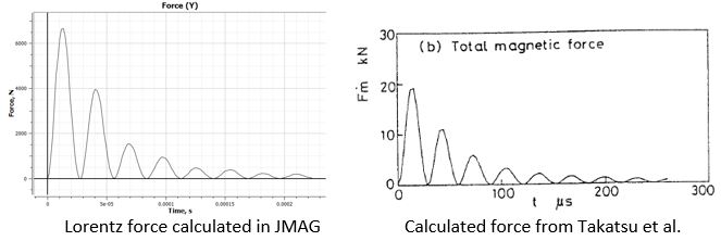
Taken into account the conversion factor due to the quarter model, the amplitude and timing from the two way coupling looks similar to the results from Takatsu and al.
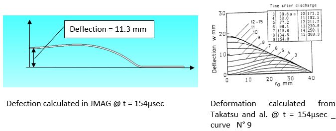
The profile of the disk could also be compared (the comparison is made for example at t = 154µsec _ curve N° 9 in the Takatsu and al results):
8. Conclusion
The results from the 2 way calculation between JMAG and Abaqus well fits the results from Takatsu and al. for this sample test case. Then, this type of calculation could be used for a more complex model including a die or a former. As, this coupling solution could use the explicit solver of Abaqus, this is a great advantage in term of speed calculation and convergence.

