We provide you with the best suited solutions to answer your requirements, objectives and projects in a comprehensive array of engineering services. The success of your projects is our main goal.
Please contact us directly at engineering@powersys-solutions.com for more details or specifics enquiries. We will be pleased to promptly answer any of your questions and find the right solutions.
Case Study
Our consulting offers are unique and tailor-made in order to answer your needs and solve your challenges. The experts of CYME from Powersys can assist you on different problematics such the following ones:
Evaluating the stability of an interconnected Power system
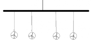
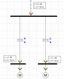
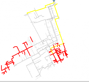
A Transmission System operator (TSO) contacted Powersys to evaluate its Power System stability. The objective was to analyze stability in different configurations (peak and slack times).
We start by importing the Power System model from another software to CYME. The model was validated with client thanks to measures on the real Power System.
The Power System is studied in normal conditions. Steady-state plants productions and load flows are determined. We identified buses where voltage limits were exceeded.
Several contingency analyses (N-1) are realized. It consists in line or transformer losses. like in normal conditions, buses whose voltage exceeds Power System limits are identified. In some N-1 cases, we established that line overloads appeared. Some solutions, as power cuts or new power dispatch among plants, are proposed.
|
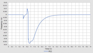
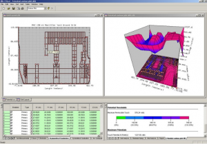
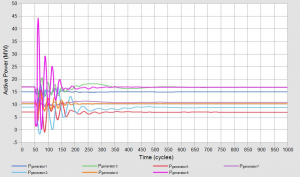
After, we performed dynamic stabilities analyses to determine if the occurrence of a fault or a generator loss could create a transient regime that would lead to an issue like the triggering of a protection or a loss of synchronism.
Thanks to this study, we determined that short-circuit simulations can provoke line tripping, a variation of frequency and a voltage drop during the fault. Generator loss simulations highlighted possible decreases in frequency. Those simulations pointed out no protection trigger.
|
|
Every studies were realized in two situations: peak period (maximum annual power consumption) and slack period (minimum annual power consumption).
Determining cable maximum ampacity
|
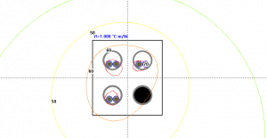
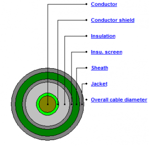
An important construction company contacted Powersys Engineering Service to investigate three cables warming. The objective of this study was to determine the maximum cable ampacity, i.e. the maximum current that can flow through these cables without reaching an excessive temperature.
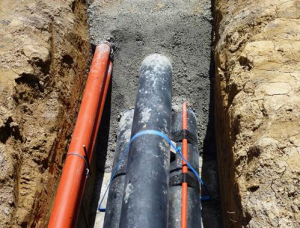
We used the software CYMCAP and modelled the cables and their environment (infrastructure earth layers). First, we reproduced geometry and materials of cables. Some data were lacking, and we used the whole set of data to estimate realistic values.
|
|
|
|
We studied several cable installations varying the number of cables, the types of cables, their configurations (trefoil/flat) or the characteristics of ductbanks/concrete fill/….
|
|
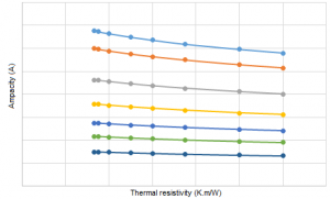
Once configurations are modelled, we calculated the maximum ampacity for each one of them. Above all, we evaluated the impact of concrete fill thermal resistivity and cable core diameter. Curves below correspond to several cable diameters.
|
|