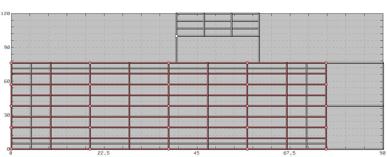
Fig2. Substation Grounding System Meshing
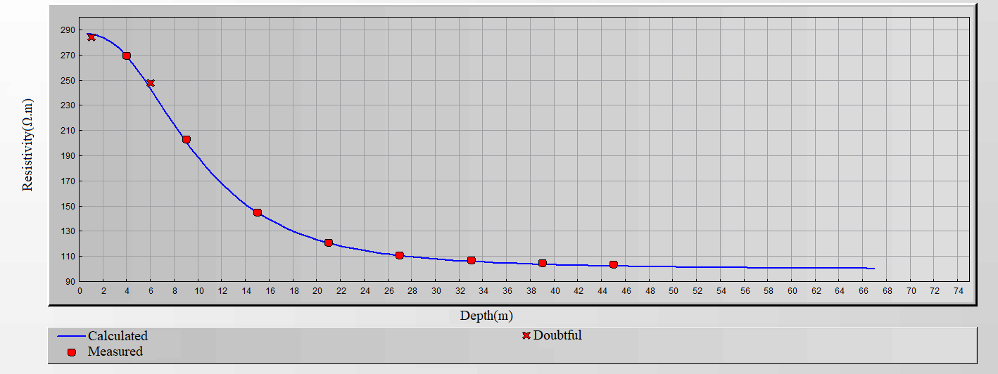
The potential rise is calculated:
Considering IEEE 80-2013 standard and expected faults amplitude and duration, we determined the touch voltage and step voltage the system had to respect to be in compliance with the current regulations.
Then, we compared the calculated maximal touch and step voltages after a fault to the limits previously determined in order to ensure touch and step voltages stay below those limits.
But we also faced other constraints. If the ground potential were too high where phone lines were buried, this can disturb the normal operation of communication lines. So, the phone network operator had established voltage limit requirements. Above all, it is very dangerous that the voltage of a natural gas pipe be too high. To ensure such a serious accident would not happen, the natural gas operator requires its gas pipe to be outside of the 650V equipotential.
Therefore, Powersys had to predict the equipotential lines at 650V and 5000V that would appear if a short-circuit happens on the substation. To do so, Powersys modelled the occurrence of a direct short-circuit. The earth potential was calculated at every point around the substation. In particular, the desired equipotential lines were calculated.
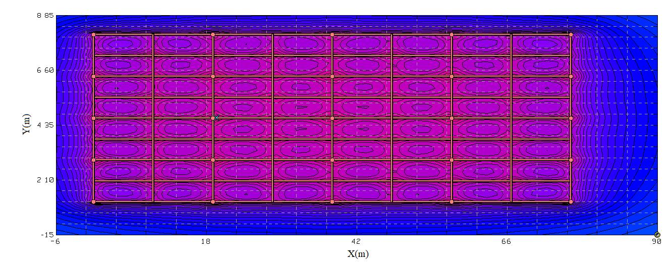
Fig3. Susbstation Surface Potentials
We were therefore able to ensure the client that the installation is conform to requirements of IEEE 80-2013 standard, phone company and natural gas operator.
We provide you with the best suited solutions to answer your requirements, objectives and projects in a comprehensive array of engineering services. The success of your projects is our main goal.