


Optimization of the design of a motor
A rolling shutters company contacted Powersys to improve a motor used in its products. In particular, the influence of motor design choices on performances had to be investigated using finite element analysis (FEA) software.
|
FEA Modelling and validation with No-load analysis:
The machine CAD is modelled in 2D using the JMAG-Designer software (a FEA simulation software for electromechanical system designs such as Generators, Motors, Transformers, …). We followed the standard procedures of FEA to build the model for the analysis. For material definition of each motor parts and to capture with more precision the magnetic and thermal behaviours of the machine, we have focus on the material properties (magnetic, electric, thermal, loss) depending on the temperature for steel and magnet parts such as BH curves, magnet Magnetization/Demagnetization curves, copper resistivity … |

Figure 1 Full and partial Motor model |
|
For mesh generation and because of rotation motion, we used the slide mesh method to generate optimal mesh elements on the parts and the rotational mesh with aligned nodes into the airgap region in order to remove the mesh noises for more accuracy of torque/force calculations. To validate this FEA model, we simulated the no-load analysis to calculate the Cogging torque and the BackEMF voltages at different rotation speeds and compare them to the experimental measurements. The obtained results showed that the FEA model settings match well with the physical experience model. |

Figure 2 No load analysis |
|
Magnetic & Thermal behaviours simulations using Load analysis: After validation of the model, we performed the followings calculations for different rotation speeds and voltage sources:
|
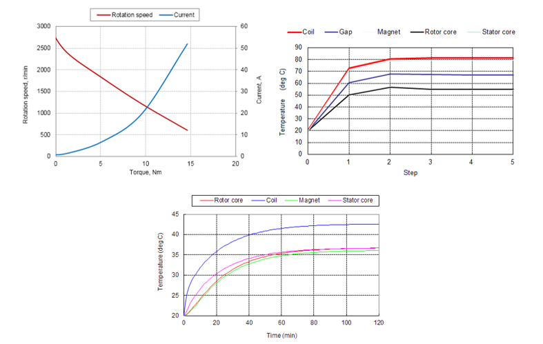
Figure 3 Current harmonics at PCC level |
Parameters Analysis for motor performances optimization
To evaluate the machine parameters that influence the motor efficiency, we built a parametric analysis to simulate:
- Different operating points: (Speeds, DC Voltages, Currents),
- Motor fault conditions (short-circuit, open circuit) at different speeds,
- Impacts of different lamination thickness of steel sheets,
- Impacts of different magnet material types,
- Impacts of different airgap lengths and shapes.
Best position of motor sensors
To find the best position where the sensors will be placed to measure with higher accuracy the maximum flux value inside the machine, we ran a parametric analysis for different position values of the sensors. Finally, the graph result of the magnetic flux versus the sensor positions was obtained, thanks to this part, we succeeded to find the location where sensors must be so that they catch the maximum flux.
Conclusion
This study not only provided the values of the manufacturing parameters to get the optimal motor performances for several motor configurations (speed, voltage, use time) but it also described the change of performances when motor parameters slightly change.

